Squirrel Cage Motor Efficiency at Partial Loading (at DOL) and during VSD Control.
There is no international standard specifying test procedures for establishing the System Efficiency of Motors + Inverters.
Generally an induction motor supplied with Voltage PWM (Pulse Width Modulated) Inverter has lower efficiency due to the additional losses caused by harmonics,
which originate in the Inverter and are amplified by long cables.
Higher switching frequencies increase the motor efficiency (reduce motor losses) but decrease the inverter efficiency (as the commutation losses are increased).
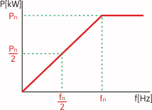
The Power Output of the inverter controlled motor is directly related to output frequency (up to the point of the base frequency):
 
The efficiency of electric motors is calculated by summation of losses.
The voltage THD (Total Harmonic Distortion) contributes to the increase of motor losses. It is generally considered that the motor losses are increased by 20% due to THD.
| List of Losses in Squirrel cage motors
|
VSD Controlled
5-50Hz
|
VSD Controlled
>50Hz
|
| No Load Losses
|
Magnetising (iron) Losses
|
Hysteresis Losses
|
Same
|
(Slightly increased)
|
| Eddy Current Losses
|
Same
|
(Slightly increased)
|
| Ventilation Losses
|
Losses in Fan and rotating parts
|
Decreased
|
Increased
|
| Friction Losses
|
Losses in Bearings
|
Decreased
|
Increased
|
| Load Losses
|
Joule (copper) Losses in Stator
|
Caused by current passing through winding
|
Increased
|
Increased
|
| Joule Losses in Rotor
|
Caused by current passing rotor cage
|
Increased
|
Increased
|
| Stray Losses
|
Used to be added as 0.5% of overall losses
|
---
|
---
|
Modern VSDs (Variable Speed Drives) or Inverters are highly efficient devices. Their efficiency is usually between 96%-98%.
The Total System Efficiency (ηT ) is then a combination of Motor Efficiency (ηm) and Inverter Efficiency (ηi).
Example: ηT = ηm x ηi = 0.90 x 0.96 = 0.864 (86.4%)
Inverters with a "good" output waveform often suffer a voltage drop. The output voltage is slightly lower than the input voltage.
|
|
|
|
|
|